

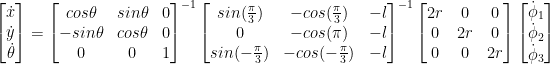
3 Wheel Omni Drive 로봇은 메카넘휠(90º) 3개를 120º 간격으로 배치하여 구성하며, 바퀴 속도의 조합에 따라 전방향으로 이동 가능하다.

식은 다음과 같이 나타낼 수 있다.
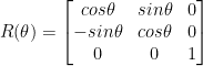
여기서,


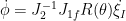
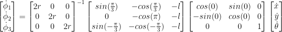
이제 바퀴의 속도 변경에 따른, 로봇의 움직임을 구하려면,
여기서 나온 결과, 즉 로봇의 속도 (
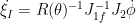
이제 로봇을 제어하기 위해서, 원하는 로봇의 선속도 (

와 같이 각 바퀴의 속도를 구할 수 있다. 이제 이 속도를 바퀴 모터에 적용하면 로봇이 원하는 방향으로 움직인다.
참고: